Global illumination algorithms used in 3D computer graphics are those which, when determining the light falling on a surface, take into account not only the light which has taken a path directly from a light source (direct illumination), but also light which has undergone reflection from other surfaces in the world (indirect illumination).
Images rendered using global illumination algorithms are more photorealistic than images rendered using local illumination algorithms. However, they are also much slower to render and are more computationally expensive.
A common practice is to compute the global illumination of a scene and store that information with the geometry. That stored data can then be used to generate images from different viewpoints for generating walkthroughs of a scene without having to go through time & resource consuming lighting calculations. For eg: Pre-calculate the photon map value for one frame, store it and use it to for other frames thus saving valuable render time that would otherwise be much more if one were to calculate every frame separately.
Different algorithms used in the process of global illumation include Raytracing, Radiocity, Photon Mapping, Monte Carlo Method, Beam Tracing etc.
How do they work?
These algorithms calculate diffuse inter-relation. In simple terms it is a process wherein light reflected from an object strikes other objects in the surrounding area, illuminating them.
Pros and cons of GI and Local (direct) illumination:
Local (direct) illumination:
1. Ray tracing does allow you to render mathematically described objects and polygons and also some cool volumetric effects, however again associated with very sharp undesirable shadows which need to be cheated
2. Shadow volumes can help you render those soft shadows which are tricky to implement.
3. The most important thing to consider is that, while these methods can produce hyper-realistic images, they can only do this when given a scene with point light sources, and perfectly shiny or perfectly diffuse objects. Now, unless you are some kind of rich simpleton, your house probably isn’t full of perfectly shiny spheres and point light sources. In fact, unless you live in a universe with completely different physics, your house probably contains hardly any super-sharp shadows. It is quite common for people to claim that ray tracers and other renderers produce ‘photo-realistic’ results. But imagine someone were to show you a typical ray traced image, and claim it was a photo. You would claim in return that they were blind or lying.
4. In other words, Global illumination is a superset of Radiosity and Ray tracing. The goal is to compute all possible light interactions in a given scene, and thus obtain a truly photorealistic image. All combinations of diffuse and specular reflections and transmissions must be accounted for. Effects such as color bleeding and caustics must be included in a global illumination simulation.
5. Many of us do prefer direct illumination methods using an omni array and faking the light bounce to cut short on expensive render times
Lets brief up each different algorithms in GI techniques:
Radiosity
Radiosity is a global illumination algorithm used in 3D computer graphics rendering. Unlike direct illumination algorithms (such as Ray tracing), which tend to simulate light reflecting only once off each surface, global illumination algorithms such as Radiosity, simulate the many reflections of light around a scene, generally resulting in softer, more natural shadows and reflections. It is a finite element method that computes a view independent GI solution as a finite mesh>>> which means that the environment is divided up into patches that are uniform and perfectly diffuse and energy is transferred amongst these patches until equalized. This tight coupling of the lighting information to the geometry is costly to calculate and meshing artifacts can occur if not carefully constructed. Radiosity also doesn’t handle arbitrary reflection models
However including radiosity in the rendering process gives an added realism to the scene as observed in the real world light, one of the most important reason being color bleeding.
Light strikes the ball, casting a shadow, in this case both the primary shadow and the contact shadow, along with the red hued color bleed on the floor
Ray tracing
Ray tracing describes a realistic method for rendering images (or frames) constructed in 3D computer graphics environments. Ray tracing’s popularity stems from its basis in a realistic simulation of lighting over other rendering methods (such as scan-line rendering or ray casting). However a serious disadvantage of ray tracing is performance since unlike scan-line it starts calculating each ray anew thus increasing the render time. It is definitely one of the preferred ways since it gives one the flexibility to shoot more rays thereby helping better anti aliasing resulting in good quality renders.
Ray traced render
In other words, Ray tracing is particularly good at simulating sharp shadows, mirrors and glass while other effects such as caustics and color bleeding are neglected.
So you see, Ray Tracing and GI have its own advantages and disadvantages
A pictorial comparison:
ray tracing: dark and sharp shadows,no color bleeding
Global Illumination: Soft shadows, contact shadows, caustics. color bleeding
Photon Mapping
Photon Mapping is a two pass global illumination algorithm. It calculates spaced photons (depending upon the various parameters)thus giving out the illumination solution which is quite powerful since it can be calculated and stored, making it very flexible for optimum rendering solutions. Of late photon mapping is also being extensively used for sub surface scattering and volume caustics.
Now as I mentioned before, photon mapping is a two pass phenomenon. Lets study them in brief.
First pass:
Photon tracing
It’s a process of emitting discrete packets of photons (in layman’s term we would call them as light energy packets) and tracing them through the scene. A photons life begins at the light source. Brighter lights emit more photons. For point light sources we want to emit photons uniformly in all directions. For area light sources we pick a random position on the surface and then pick a random direction in the hemisphere above this position. The emission strategy can be changed depending on the scene. For example, for sparse scenes we want to focus our photon emission at the geometry or most photons will be lost
Photon Scattering
Emitted photons from light sources are scattered through a scene and are eventually absorbed or lost. When a photon hits a surface we can decide how much of its energy is absorbed, reflected and refracted based on the surface’s material properties.
As each photon is bounced or refracted by intermediate surfaces, the energy gets absorbed until no more is left. We can then stop tracing the path of the photon. Often we stop tracing the path after a predefined number of bounces in order to save time.
Diagrammatic representation of Photon scattering
Photon Storing
For a given scene we may shoot millions of photons from the light sources. It is desirable that our photon map is compact to reduce the storage costs. Photon mapping is generally a pre-process and is carried out before the main rendering of the image. Often the photon map is stored on disk for later use. Once the actual rendering is started, every intersection of an object by a ray is tested to see if it is within a certain range of one or more stored photons and if so, the energy of the photons is added to the energy calculated using a standard illumination equation. The slowest part of the algorithm is searching the photon map for the nearest photons to the point being illuminated.
Photons being calculated
Second pass Rendering
The calculated photons which have already been stored on the HDD can now be used to render your scene, thus saving valuable render time consumed while calculating the photon emission, which preferably is one of the best methods used during rendering a batch of frames. eg:walkthroughs
Caustics & Photon Map
During the photon tracing phase a separate photon map is used for caustics. Otherwise many more photons would be needed in a single photon map to produce good caustics. In other words,greater the number of unnecessarily accumulating photons,more is the render time,which is undesirable. Hence for sharper caustics, a filter can be used such as cone filter. However rendering caustics is fairly straightforward as you can directly visualize the photon map.Given below is an example of caustics calculated with photon mapping.(Caustic generation with photon mapping will be explained in depth in one of the forthcoming articles)
Indirect Illumination with photon mapping
Indirect illumination is much trickier to get right. In this case, the information from the photon map can be used in a more accurate solution such as path tracing. However, good results can be obtained using photon mapping directly. Often times a final gathering step is employed to improve the results using the photon map. Even without a final gather step it is possible to achieve images such as the one below
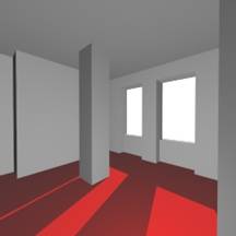
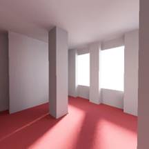
The image on the left shows the contribution from direct lighting only and the image on the right was rendered using photon mapping. No final gather used. Notice the color bleeding in the second image.
Contribution of Direct light Photon mapping without final gather
The scene has been set up to show the effect of radiosity or photon mapping which is solely responsible for color bleeding.No indirect illumination and/or final gather would mean no color bleeding.So the first img indicates only direct illumination..no secondary bouncing..2nd img specifically explains color bleeding..that is different colors bleeding on the floor and the sphere.

